Joint design

Sealant joint design basics: movement, depth and backing

Understand how substrate movement, joint width and depth, two-sided adhesion, backing, installation temperature and access shape a durable seal.

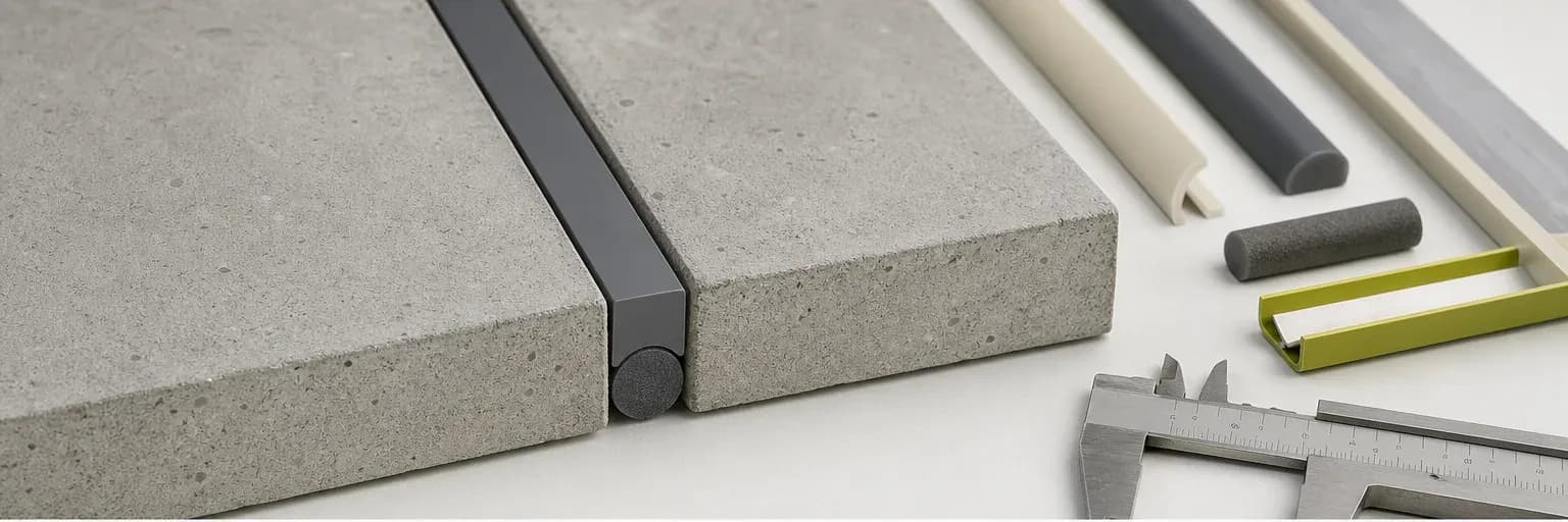
Architectural joint cross-section showing two bonding faces, backer rod and an hourglass-shaped sealant bead
Joint width, depth, backing and two sound bonding surfaces determine how well the sealant can stretch and compress.

Short answer

What to know first

A movement joint must be wide enough for the expected opening and closing, shaped within the selected sealant’s dimensional limits, and normally bonded to the two opposing faces rather than the back. Backer rod or bond-breaker material controls depth and adhesion. Product movement class alone does not size the joint: assembly movement, installation temperature, substrates, exposure and the current TDS or engineered detail must be considered together.

The visible bead is only the exposed part of a joint seal. Its performance depends on how far the surrounding materials move, the temperature at installation, the condition of the edges, the backing and primer, and the shape of the sealant between the two faces. A strong product in the wrong cross-section can be strained beyond what the detail allows.

This guide introduces questions for ordinary building joints and supports the application selector. It is not an engineering calculation, structural-glazing design or project approval. ASTM C1193, the selected product’s current TDS and the responsible designer control the final detail.

Estimate movement before setting dimensions

Joints open and close because adjacent materials expand, contract, dry, deflect or settle. Temperature range, material coefficients, panel length, moisture change, loading and construction tolerance all contribute. The expected movement is not simply the gap visible on the inspection day. Ask the designer for calculated movement on significant work instead of treating a photograph or one site measurement as the design range.

Movement is usually considered in relation to the installed joint width. If the same absolute movement occurs in a narrower joint, the percentage strain is greater. Installation near one temperature extreme can leave more travel in one direction than the other. A movement classification in a product document is meaningful only when the test, installed geometry and project movement are understood together.

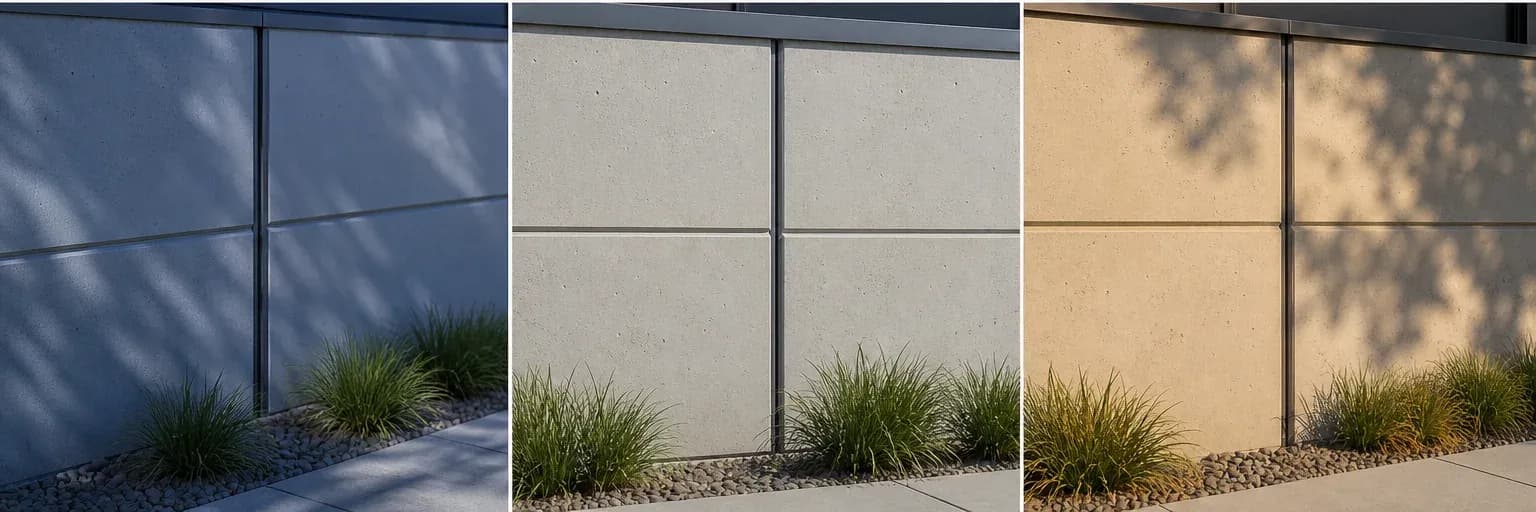
Three views of the same façade joint at cool, installation and hot conditions with changing width
The installed width sits inside a movement range; designing from only the current gap can understate future extension or compression.

Joint width and depth work together

Joint width leaves room for movement and enough surface for adhesion. The right depth lets the sealant stretch and compress without becoming an unnecessarily thick plug. Manufacturers publish different size limits and width-to-depth guidance for different products and uses. Follow the current TDS or project detail rather than applying one brand’s rule to another product.

Avoid feathered edges and abrupt thick-to-thin transitions. A shallow smear can tear or detach, while excessive depth may slow cure and change how stress is distributed. Corners and irregular openings should be repaired or detailed so the sealant has sound, reasonably parallel bonding faces. Quantity estimates should follow the designed section, not decide it by encouraging the thinnest possible bead.

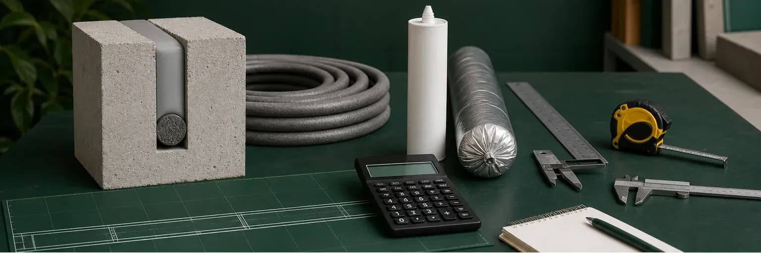
Volume follows the designed cross-section

Bonding on two sides allows movement

A conventional movement joint is normally intended to bond to the two opposing sides and remain free at the back. When the sealant also bonds to a third surface, movement can pull it in competing directions and concentrate strain. The resulting tear or edge loss may be blamed on chemistry even though the cross-section prevented the material from moving as intended.

Use an approved backer rod or bond-breaker to prevent rear adhesion. The two bonding surfaces still need correct preparation and any specified primer. Corners and other three-dimensional intersections need their own project detail; the simple two-sided diagram does not fit every shape.

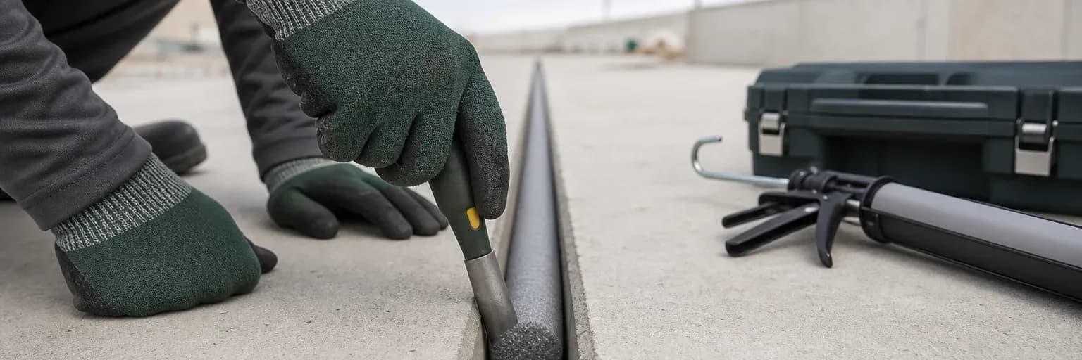
Inspect the backing before applying sealant, because it will be hidden once the bead is finished.

A movement joint needs two bonding faces

Choose backing to suit the joint

Backer rod can establish depth, support tooling and create the non-adhering rear profile. Closed-cell and open-cell foams have different handling and moisture characteristics. Size should create the intended fit without damaging the rod or distorting the joint. Puncturing closed-cell material can release gas into fresh sealant; over-compression or an undersized loose rod can also undermine control.

Where a joint is too shallow for a rod, an approved bond-breaker tape may prevent rear adhesion without adding depth. Neither accessory is generic packing. Absorbent rope, expanding foam scraps and other improvised fillers can introduce moisture, chemicals or an unstable surface. Read when to use backer rod and follow the product/detail rather than choosing only by convenience.

Provide sound surfaces and room for preparation

Sealant bonds to the edges presented to it, not to an idealised material name. Concrete may carry laitance; masonry may crumble; metal may be oily or coated; a cut joint may expose incompatible filler. The detail should leave enough accessible face for preparation, primer and tooling. Weak edge material can break away even when the sealant itself remains firmly adhered.

Compatibility with coatings, membranes, gaskets, glazing components and previous sealants must be considered. Plasticiser migration, staining and corrosion are not solved by increasing bead size. Use project adhesion or compatibility testing where the manufacturer or specification requires it. The adhesion testing guide explains the difference between screening and formal evidence.

Plan for drainage, inspection and replacement

A joint detail should not create a shelf that retains water or direct runoff behind the bead. UV, heat, cleaning, traffic and chemicals affect the product shortlist and the protection needed during cure. Horizontal traffic joints, immersion, façade joints and sanitary perimeters are different systems even if a cross-section looks similar. Confirm that the selected product and accessories cover the actual orientation and exposure.

ASTM C1193 notes that service life is influenced by design, compatibility, installation, environment and maintenance. Provide access for inspection and eventual replacement rather than burying a serviceable joint behind permanent finishes. Link the final detail to current documents, batch/installation records and an inspection plan. The exterior maintenance guide develops that lifecycle view.

Finish the design with a joint schedule that can be inspected. For each joint type, record its location, surfaces, allowed dimensions, expected movement, backing, sealant and primer, finish, exposure, access and replacement method. Coordinate drainage, membranes, flashings and coatings so the sealant is not expected to do another component’s job. At handover, keep the approved mock-up, current documents, batch records, photographs and inspection results. Future teams can then identify ageing and judge whether a local repair is compatible.

Review the schedule whenever an opening, finish or supplier changes. A substitute that looks equivalent on a drawing can change bond width, primer, backing or movement assumptions. Update both the joint details and the named material.

Decision aid

Questions to answer before sealing the joint

How far can the assembly move?

Use material, temperature, moisture, panel length and loading information; do not size from one observed gap alone.

What joint size does the product allow?

Confirm width, depth, minimum bond face and movement range in the current TDS or engineered detail.

How is rear adhesion prevented?

Specify the compatible backer rod or bond-breaker and installation method rather than relying on improvised filler.

Can it be prepared, inspected and replaced?

Provide sound accessible faces, drainage and a realistic maintenance route for the expected service life.

Evidence

Primary sources used

  1. ASTM C1193-25 — Standard Guide for Use of Joint SealantsASTM International

    General joint-design, substrate-preparation, backing, primer, installation, environmental and maintenance considerations; explicitly excludes structural glazing.

    Accessed 16 July 2026
  2. ISO 11600:2002 — Classification and requirements for sealantsInternational Organization for Standardization

    The principle that building sealants are classified by application and performance characteristics rather than by a generic chemistry name alone.

    Accessed 16 July 2026
  3. Joint sealants for building and civil engineeringSika

    General explanation of joint dimensioning, backing rods, three-sided adhesion, substrate condition and application workflow; not Pereseal-specific evidence.

    Accessed 16 July 2026
  4. FAQ and technical bulletinsBostik Singapore

    General industry guidance on backing rods, joint dimensions, primers, paint cracking, inspection and sealant terminology; not evidence for Pereseal product performance.

    Accessed 16 July 2026

Next step

Check the joint design against the product TDS

Compare movement, dimensions, backing, surfaces and exposure with the current TDS before choosing a Pereseal product.

Review construction joints

Related documents

Read the product evidence beside the guide

Technical data sheetEN

Pereseal N TDS

Technical datasheet for Pereseal N neutral cure silicone.

Relevant starting points

Products mentioned in this guide

These are selection starting points. Confirm suitability in current product documentation.

Neutral silicone

Pereseal N Weatherproof Neutral Seal Silicone

Product details

Keep learning

Related evidence-led guides